Voltage Control
Applets
significance of voltage control
   Typical ranges of quantities

      active power      P =  (-100% ...) 0% ... +100%

      reactive power    Q = -100% ... + 100%

      current           I = 0% ... 100% Ir  (rated or nominal value)

      voltage           U = ?


   why not U = 0 ... 100% in 400 V (low voltage) level ?

      house hold consumers, equipment   95% ... 105%

      => LV  U = 95% ... 105% (acording to country specific standards)


   why not 500 kV in 400 kV voltage level ?

     insulation of lines and cabels, switches

     insulation and saturation of transformers


   why not 300 kV in 400 kV voltage level ?

      consider: PLoad = 3 U I ,  QLoad = 0

      I = PLoad / 3 U

      I high for low U

      reduced transmission capacity

      increased losses

         PLoss = R  | I | ^2


      => EHV, HV  U = 90% ... 110%
causes of low voltages
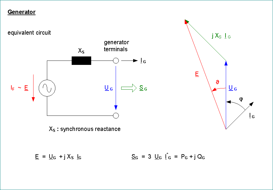
source voltage
generator terminal voltage
transformer ratio / tap setting
voltage drop
line length, load current
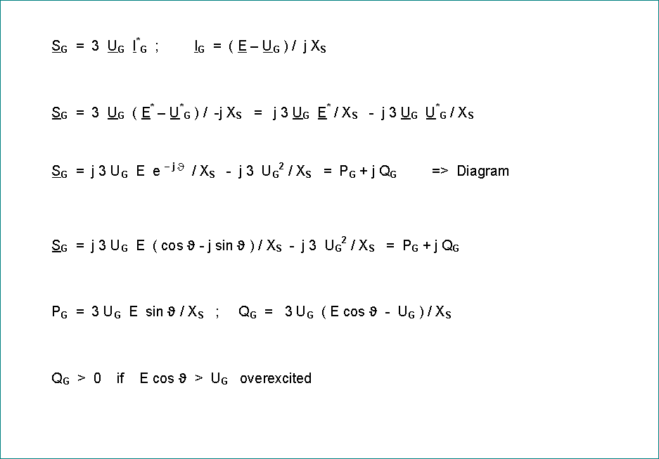
S = 3 U * I*
I = ( P - j Q ) / 3 UL*
US = UL + ( R + j X ) * I
US = UL + ( R + j X ) * ( P - j Q ) / 3 UL*
for UL = UL + j 0
US = UL + ( R P + X Q + j ( X P - R Q ) ) / 3 UL
real part: aprox. = absolute value = voltage magnitude
imaginary part (small, phase angle between US and UL)
for HV and EHV R << X (~10%)
voltage magnitude mainly governed by Q
phase angle mainly governed by P
(remember dU/dQ >> dU/dP for transmission lines)
means of voltage control
- transformer taps
- injection of reactive power
- shunt capacitors
- shunt reactors, compensation coils
- generator, excitation system, P > 0, Q < 0 or Q > 0, generator terminal voltage
- phase shifters, synchronous condensors, P = 0, Q > 0 or Q < 0
- static var compensation, semiconductor controlled capacitors and reactors
- series compensation of long transmission lines
- (DC transmission)
load flow calculations
   Free load flow demo:   Power World Simulator

   given:

      P, Q for all load buses

      P, Q or P, U for generator buses / power injections"

      data of lines and transformers


   find:

      U, <)  for all buses

      I, P, Q for all branches

      Q for P,U generators

      active and reactive power losses
         single branch
         total netzwork


   load flow equations => nonlinear set of equations ( 2 x number of buses)

      Newton-Raphson-method